A powerful feature of VisualApplets is to combine the images of different camera sources. In the following we will learn on how to
- switch between camera sources
- overlay the images of two cameras
- multiplex the camera images
- stitch the images of two cameras
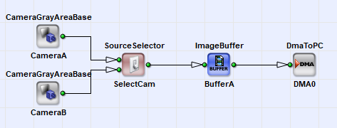
To switch between two cameras, we need a simple design including two camera modules. In VisualApplets operator SourceSelector (see 'SourceSelector') can be used to switch between two asynchronous sources. This operator allows the selection of one of it's inputs, while the data on the other inputs is discarded. If one of the inputs is selected, the others behave like they are connected to a Trash operator. It is possible to switch the inputs while the acquisition is running. The operator will switch with the start of a new frame. The frame rate and image sizes of both inputs do not have to be the same.
In the following, we will have a look on how to combine the image data of both cameras. In our example, we use an overlay-blend to combine both images.
The specification for our example will be:
- Camera: Two CameraLink RGB area scan cameras in base configuration mode
- Resolution: 1024 x 1024 pixel
-
Overlay-Blend:

-
Basic Operators
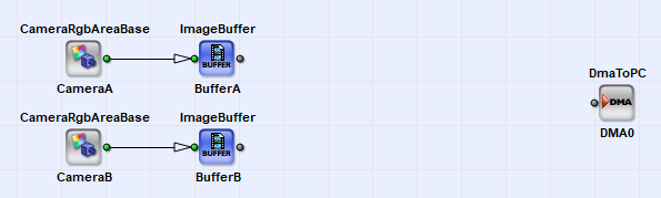
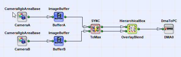
We start with the basic operators in our design as shown in the following figure. We can use all the default parameters and link properties.
-
Synchronization
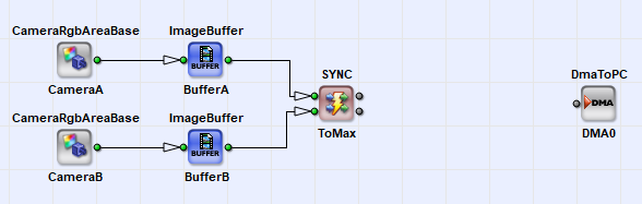
Next we need to synchronize the data streams of both cameras. This can simply be done by using operator SYNC. The SYNC operator controls it's inputs so that the outputs are fully synchronized. As you can see, we used two buffer modules before the synchronization. We need to use them because we cannot ensure that both cameras are 100% synchronous.
Although we synchronized our image data, we still need pay attention to some constraints:
-
The number of frames i.e. the frame rate of both cameras has to be the same. If one camera has a higher frame rate than the other camera, one of the ImageBuffer modules will need to store some images and might get in an overflow condition. Thus, for a long time acquisition, both cameras have to acquire their frames using the same frame rate. A trigger system can ensure this.
- The image size and the image position of the ROIs of both cameras may differ. The SYNC operator will, depending on it's parametrization, automatically expand the smaller image to the larger one or cut the larger image. See the description of the SYNC operator for more details: ('SYNC')
-
-
Overlay-Blend
The last step to do is to implement the overlay blend to combine both images. For convenience, we use a hierarchical box for the overlay-blend implementation.
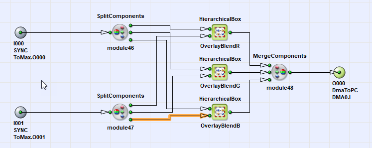
The overlay blend has to be individually applied to all color components. Thus we need to split our links into all three color components. The overlay blends are placed in hierarchical boxes once again. Thus we have three hierarchical boxes inside the current hierarchical box. You can use copy and paste to duplicate the boxes for each color component.
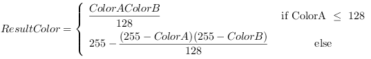
We will have varying possibilities to realize the equation given above using VisualApplets operators. In general, you should always try to adapt and optimize an equation for FPGA use before implementing it.
The equation includes some multiplications and divisions with constant values. These operations are available in VisualApplets but cannot be very efficiently implemented on FPGAs. If the multiplication or division can be written as a power of two multiplication we can use a simple bit shift for implementation. A bit shift will require no resources at all! We will simplify

to

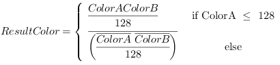
which is a simple right shift by 7 bit i.e. we discard the seven least significant bit.
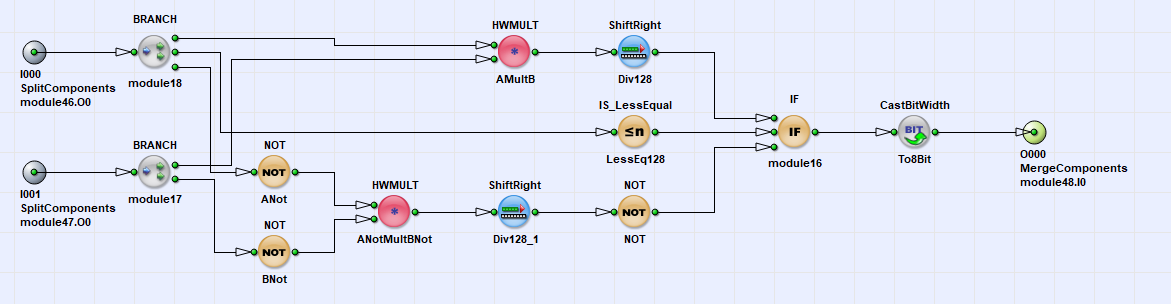
Next, there are some parts in the equation like 255 minus ColorA. This is a simple color inversion. White becomes dark, dark becomes white. An inversion of an value can also be made using a simple inversion of each bit. This allows us to finally rewrite the equation:
We can now start our implementation. The remaining operations in the equation are available as VisualApplets operators. We will need
-
IF
-
NOT for the inversion
-
ShiftRight for the division by 2^7
-
HWMULT for the multiplication
Besides HWMULT, VisualApplets includes the MULT operator. The do the same, but HWMULT will use dedicated multiplier in the FPGA and therefore, will require much less resources.
-
For bit depth limitation, we will need a CastBitWidth operator. This operator can be used to switch from 9 bit to 8 bit by discarding the MSB. From the formula we know that there will be no values greater than 255.
-
-
Verification using the Simulation
-
We can easily verify the functionality of our overflow-blend using the VisualApplets simulation. Use two simulation sources to inject an image for both cameras. Place simulation probes to any link you like. The simulation results will show you the overlay of both images. If interested, you can also check the intermediate results of the overlay in the hierarchical boxes.
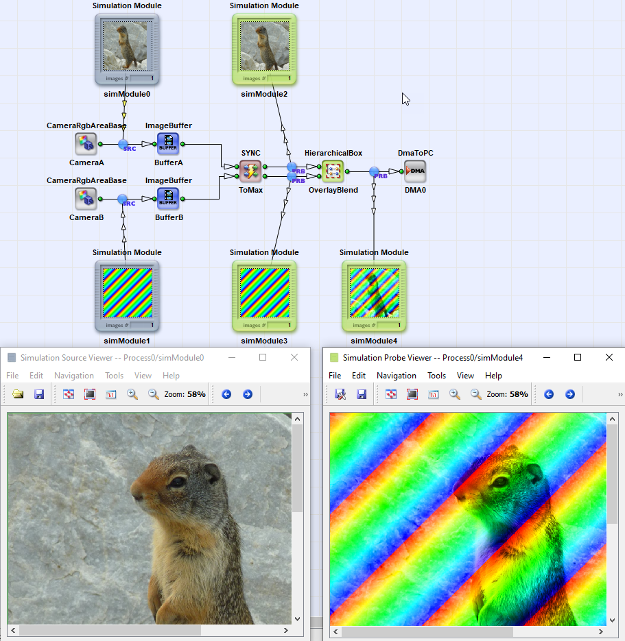
- The verification of the synchronization is not possible with the simulation as the simulation will only reflect the functional parts of the applets and not the timing. A verification in hardware is required.
-
-
Adding a Trigger
As mentioned, both cameras have to run at the same frame rate to avoid an overflow on one of the buffers. This can be easily solved using a trigger system.
The multiplexing of images or lines in VisualApplets is very easy. We will start with the example of multiplexing the images of two cameras i.e. we want to use the same DMA channel to alternately output the images of camera A and camera B.
-
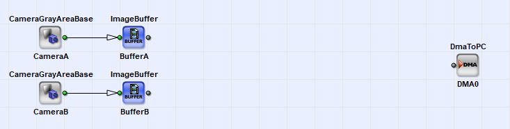
Basic Operators
We will need the standard design for two cameras using two cameras modules, two buffers and one DMA.
-
Multiplex Images
To multiplex the images, we use operator InsertImage. This operator will forward the images of it's inputs one after another. For example, if we use two inputs, the operator will forward the images of input 0, 1, 0, 1, 0, 1, ... Thus, after one input has been processed, the next one will be used. Therefore, it is required that the number of frames at both inputs is the same i.e. the inputs will have the same frame rate.

As you can see, we placed the image buffer modules before the insertion. This is because the InsertImage operator has no buffer itself. While images of input 0 are forwarded, input one is blocked, thus camera images need to be buffered to avoid the loss of data.
For each input (I0, I1, ..) the operator provides a second input called Ins0, Ins1, ... This input is a control input to control whether images shall be used or discarded. Thus an input can be skipped if value 0 is at the Ins input and will be used if value 1 is provided. The input groups I and Ins have to be synchronous, i.e. they have to be sourced by the same M-type operator through an arbitrary network of O-type operators. See 'Operator Types' for more information. As both inputs are synchronous, they will need to have the same image dimension. InsertImage will use the first pixel on the Ins inputs to decide whether an image is used or discarded. As you can see in the previous screenshots, we simply used a CONST operator to enable the use of the images. Set the output link bit depth of the CONST operator to one bit and the parameter "Value" to 1 to enable the insertion.
Please note: If the value at one of the Ins inputs is zero, the operator will still need to process the images on this inputs. A value zero does not mean, that no image has to be provided. If no image is provided at an input, the operator waits until an image is available.
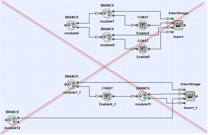
As mentioned always one of the inputs is opened at a time, while the others are blocked. The images have to be sourced asynchronously e.g. from different buffers. In the following figure, you can see two configurations which will not work. You will not get any results from the applet as it is blocking itself. It is a so called "deadlock" condition.
Always check if one of the inputs can be buffered when stopped, while the other one is active. Do not forget that deadlock situations cannot be detected by the DRC nor the simulation. More information on deadlocks can be found in 'Timing Synchronization'.
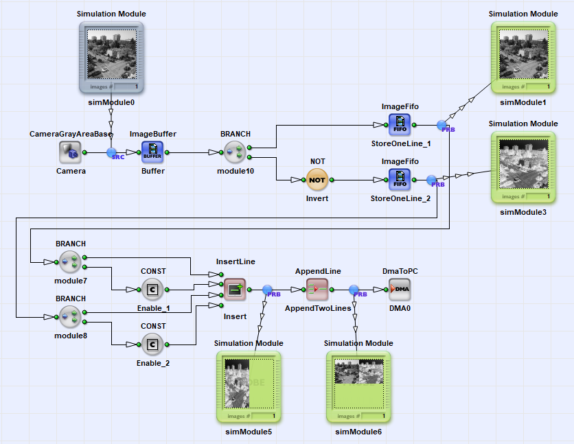
In the previous section we multiplexed two cameras images. Stitching is almost done in the same way. We use operator InsertLine instead and need to append two successive lines using an AppendLine operator.
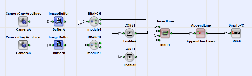
InsertLine will first multiplex the lines of both inputs and after, we need to append two lines.
Of course, it is possible to use the same image source for the last two examples, too. The only thing we have to care is that we have sufficient buffers before the insertion. For inserting an image, we will need to buffer a full image. For duplicating a line, we simply need to buffer one of the lines, while the same line is processed on the other path. To buffer only a few lines we can use operator ImageFifo. This operators will not use frame grabber DRAM memory. Instead, it uses the FPGA internal BlockRAM memory. We will configure the FIFOs to store a maximum of one line. In the following example, we duplicated an image line, where the duplication is inverted. Thus our result is the original image on the left, and the inverted (negative) version on the right.